Have you ever wondered what happens to your oil after you’ve sent it to our laboratory? In this blog series, we will be discussing some of the tests your oil may be put through and how they give us an insight into the health of your equipment.
A Day In The Life Of An Oil Sample.
Inductively Coupled Plasma Optical Emission Spectroscopy (ICP-OES).
Big in name and big in nature, the ICP is one of the most important tests a sample will take in the laboratory, producing a wealth of data about the elements in your oil.
How it works (the basics – TLDR)
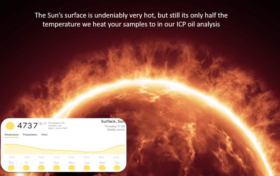
Firstly, a small sample of oil is taken from the bottle and added to a solvent usually white spirits, the same stuff you clean your paintbrushes with, although some mistranslations from English to other languages and back again in textbooks often call this solvent kerosene. The ICP vaporises the sample in a nebuliser and sprays it through a plasma (flame) that is twice as hot as the sun’s surface temperature. As the sample particles enter the flame, they get very hot and the individual atoms get very excited by all this energy. When they leave the flame, they release this energy as light and a detector looks for the unique signature wavelength of each element. This is similar to how you put different metals in a flame at school they glow in different colours. Since the amount of light released is related to the concentration of each element present, the lab can determine how much of each element is present in a sample. A normal ICP test can only detect particles below 5 microns in a sample (the wear particles that matter are all above 15 microns), but our exclusive LubeWear ICP analysis gives more accurate data when looking for larger particles (see below for further information).
Our ICPs aren’t restricted to just oil, they can also test, fuel, AdBlue, coolant and grease. If you already send us these samples from your equipment they’ll also be tested on an ICP. If you’re not sending us these samples, now is a great time to talk to a member of our team about expanding your testing program and all the benefits it will reap!
Detailed explanation of ICP for the curious readers (skip for those who just wanted a brief overview above)
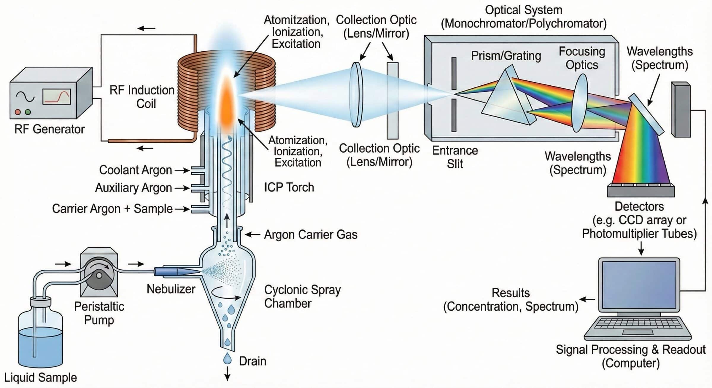
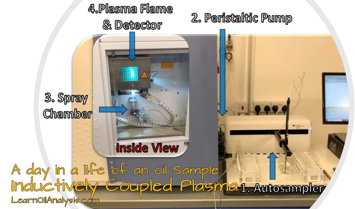
Above is the full diagram of the ICP process in how it works start to finish which can be daunting, so let’s break it down into small manageable chunks.
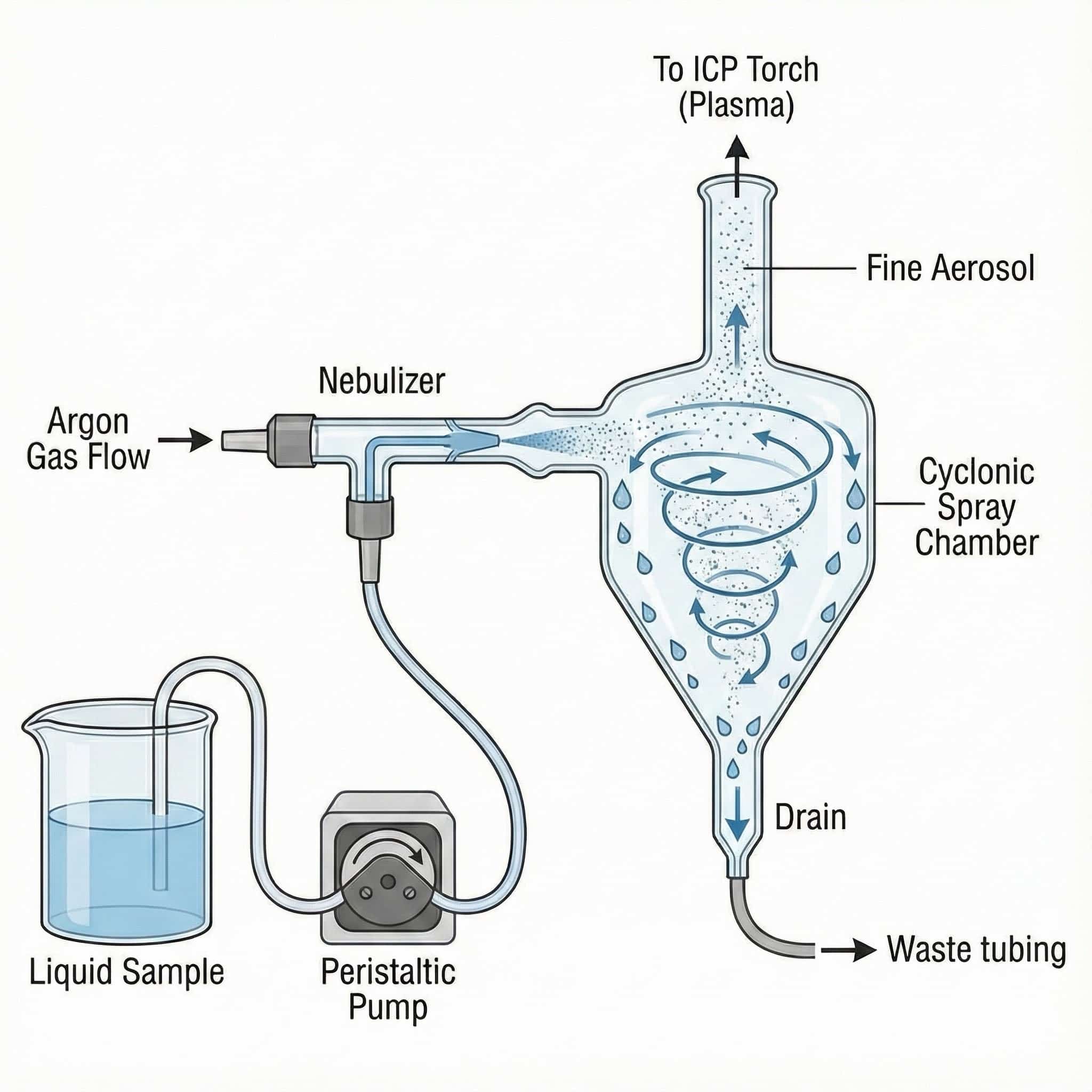
So first we have a peristaltic pump to pull the liquid from the sample vial (usually the oil in a solvent like white spirits). This meets a flow of argon gas coming in which nebulises the liquid to make a mist that cycles round the spray chamber (there are multiple styles of chamber available). In this chamber the heavy droplets drop to the bottom leaving a nice mist to travel up with the argon flow up to the torch.
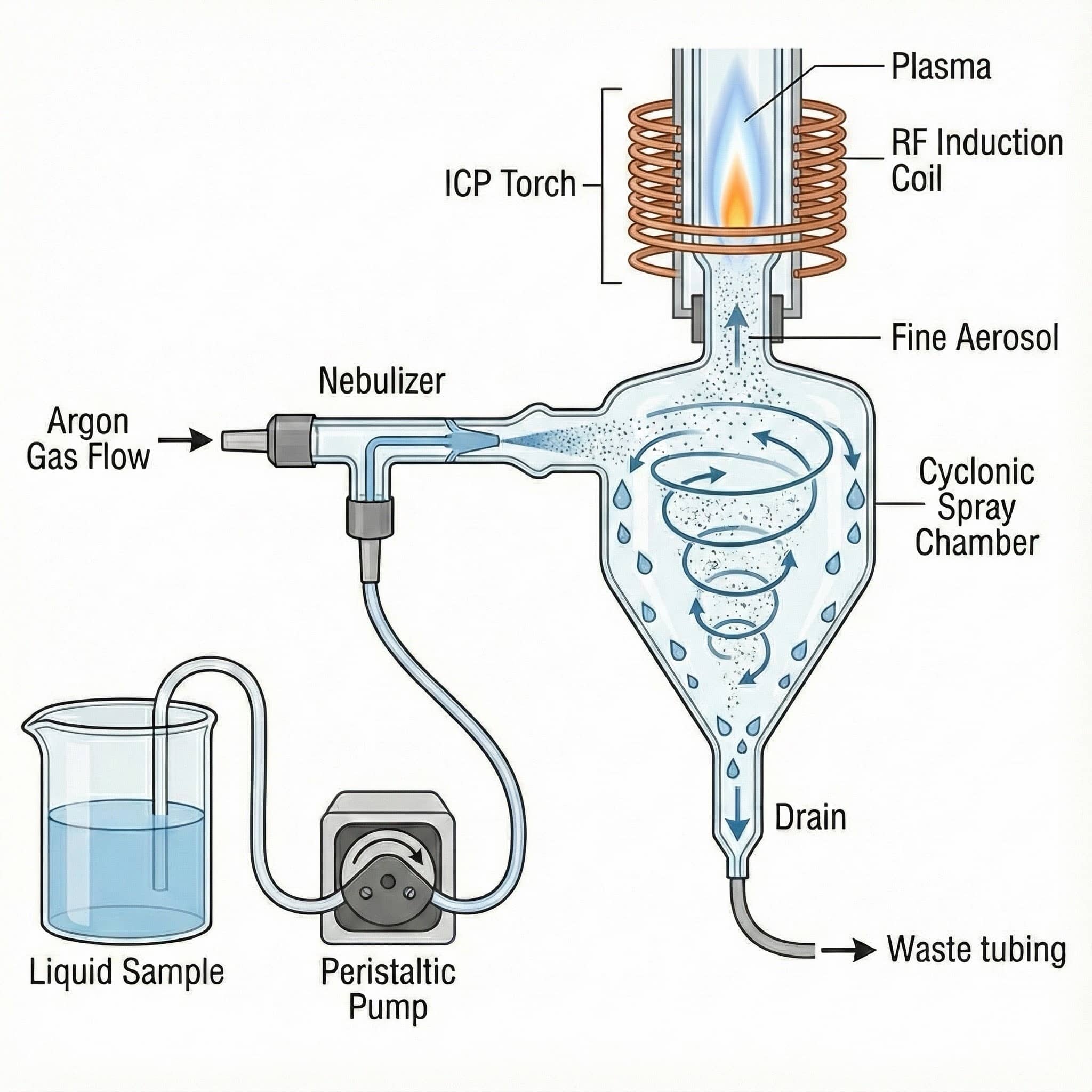
We can’t see the torch yet, so let’s now add on the torch and coil. In reality the gap between torch flame and the spray chamber is larger but this is to illustrate the principles and is not to scale. So we can see the flow of argon with a fine aerosol of sample goes up toward the flame.
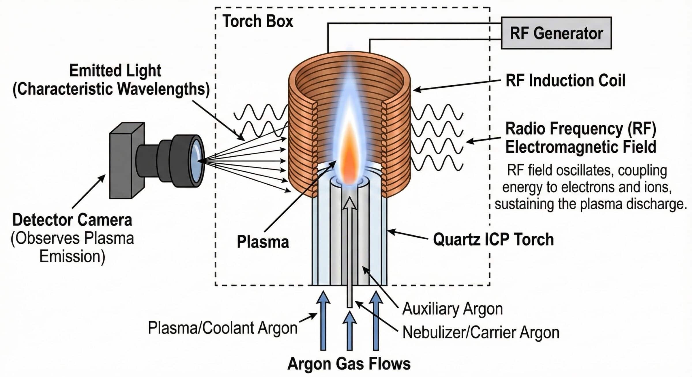
Now let’s look at the torch and detector in detail. The centre of the flame is about 10,000C, twice the surface temperature of the sun. The argon is an inert noble gas and is made into a plasma (the 4th state of matter after solid, liquid and gas) by radio frequencies waves circulating around the torch. Argon is also used to cool the coils and surrounding torch areas, similar to how engines use oil to cool the piston heads etc.
What is plasma?
We mentioned plasma, let’s just recap what plasma is. Plasma is an ionised gas ie a gas where it has lost its electrons meaning it can be shaped with magnets (the RF waves) to hold it in place. They also can move the electrons back and forth very quickly generating movement and molecular friction (think rubbing your hands together to get warm much faster and at the atomic scale). This generates phenomenal amounts of heat.
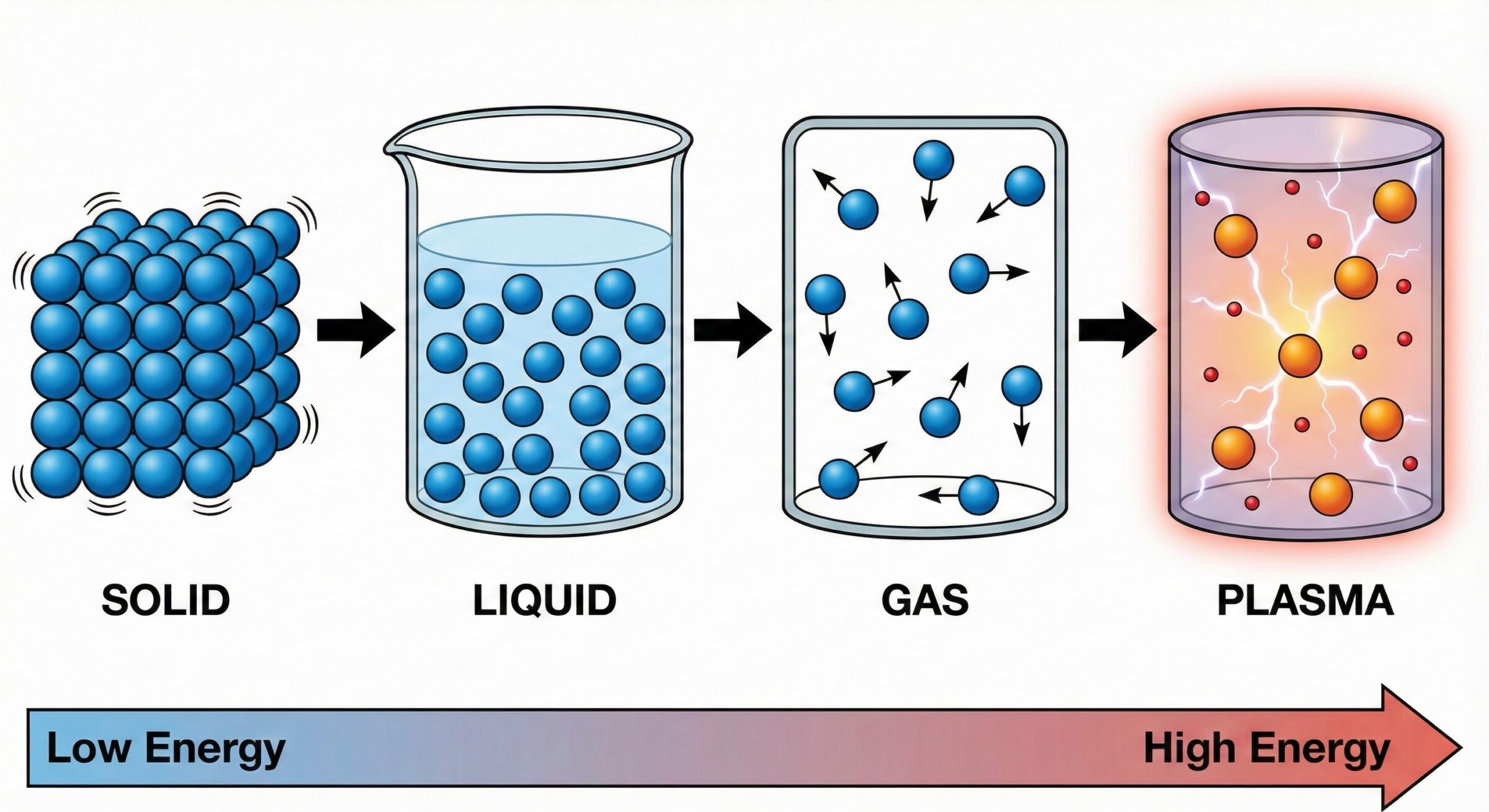
Although we think of solid, liquid and gas the main states of matter plasma is actually very common and in fact if you look up at the night sky most of everything you can see is plasma as 99% of all visible matter in the universe is plasma including the sun, stars and lightning. So in reality the ICP plasma is more normal state of matter than you think.
In the plasma flame the aerosol reaches the very hot plasma and itself is vaporised and its electrons excited. As it leaves the tip of the flame and cools its electrons lose the energy they have just taken on and fall back to a non-excited state. In reality billions or trillions of atoms are all being excited at once, but let’s explain on one atom to begin within.

The traditional diagram of an atom looks something like below. Modern quantum mechanics enthusiasts amongst you will probably laugh at the simplification here, but if you think of an atom with a nucleus of protons and neutrons with electrons orbiting in shells like planets when an atom gets excited the electrons move further away. When they cool (the yellow electron in the image) they lose that energy as light. Each element gives specific wavelengths of light which can be detected.

A common way to explain ICP is the flame test. You will have at school probably put something in a flame and it changes colour. That is essentially the ICP element identification principle.

The light passes through a prism to split the wavelengths and a photomultiplier tube and detectors amplify the wavelengths detected and give a count of photons at each wavelength. Using a calibration curve with known standards the lab can work out what elements are present with incredible precision.

Traditional Limitations of wear particle size on ICP
Most of a lab report is made up of this test alone. Imagine being in a microscopic space ship made of iron passing through from the nice 20’c lab environment to 10,000C plasma for a couple seconds. It’s probably a pretty scary environment, but if you are big enough your ship would probably survive the ordeal.

Large wear particles are inherently more insulated from being vaporised than their smaller particles. Hence the solution is to digest the particles to make the smaller and hence easier to measure. We will now cover the size limitations of ICP and the solutions.

So why do wear particles get under-represented?
First and foremost if you are pumping material if you don’t have enough agitation the heaviest particles probably never get aspirated in the first place or even are too big to go up the peristaltic tubing. Once those heavy particles that do get aspirated reach the nebuliser the spray chamber will prioritise the time aerosols and the heavy particles will simply touch the bottom and go to drain never reaching the flame.

In the event that some of those large particles actually meet the flame, the smallest particles will be fully vaporised, but the largest particles will largely remain intact.

If we compare 30mg of iron in one clump or 30 x 1mg the same total mass exists but the surface area gives far more light generation. Hence to truly measure large wear particles you need to make them smaller so they can be fully measured.

LubeWear Analysis.
In steps acid digestion, a technology known for around 70 years, but its complexity has always made it not a viable option to be cost effective but modern techniques like LubeWear make it far more viable and cost effective to perform.

LubeWear analysis is an award-winning method developed and used exclusively by Oil Analysis Laboratories. Traditional ICP oil analysis can only detect particles below 5 microns; to put this into perspective a human hair is 80 microns, meaning if there are any particles visible to the naked eye in your sample, an ICP can’t detect them. This is worrying as any large particles in your oil are what will be causing the most amount of damage to your equipment but cannot be detected and analysed by the testing done by most laboratories. In 2018, we developed LubeWear after years of research to rectify this issue. LubeWear testing is able to detect all particles in a sample, including the ones over 5 microns. We strongly believe in offering the best service and quality of data possible to all our customers, therefore, LubeWear analysis comes as standard with every sample without any extra cost to you.
As can be seen from the diagram below a wear particle sample will have a mix of small and large particles. Measuring by standard elemental and acid digestion gives the mix of normal and abnormal wear particles.

What does it tell us?
LubeWear and traditional ICP testing detect the levels of over 20 elements in a sample and the data produced is collated and sent to our team of diagnosticians for analysis. They look through this information to see whether the amounts of each element found to fall into normal or abnormal limits for the type of oil and the ratio between normal and abnormally sized particles. The diagnosticians look at this information alongside the data from other tests to conclude the condition of the oil and any effects this may be having on your equipment. If any element levels are found to be abnormal, this is written into the report produced with an explanation for why this could be occurring and any corrective actions that may need to be taken to protect your equipment e.g., abnormal levels of aluminium in an engine oil could indicate piston wear and a solution could be to inspect the condition of your air filters.
If you’re interested in learning more about oil analysis, press the contact button below to contact a member of the team or as a bonus watch a video summary below that delves into more detail on ICP