

Lubricant additives are designed to be sacrificial—they protect equipment by depleting themselves through chemical reaction, physical removal, and surface adsorption. Understanding exactly how each additive type fails reveals the key to extending lubricant life and preventing costly equipment damage. This comprehensive guide examines all known additive degradation pathways, from the acid-base reactions consuming your TBN reserve to the subtle electrochemical effects now emerging in electric vehicle applications. For maintenance professionals and lubrication engineers alike, mastering these mechanisms transforms oil analysis from reactive troubleshooting into predictive asset management.
Modern lubricants contain 10-30% additive packages by volume in engine oils, with even “lightly additised” turbine oils requiring precise antioxidant protection. These additives perform three essential functions: enhancing base oil properties (viscosity index improvement), suppressing undesirable characteristics (pour point depression), and providing entirely new capabilities (anti-wear protection). When additives deplete beyond critical thresholds, catastrophic equipment failure can follow within hours—making additive integrity monitoring one of the most valuable activities in any reliability program.
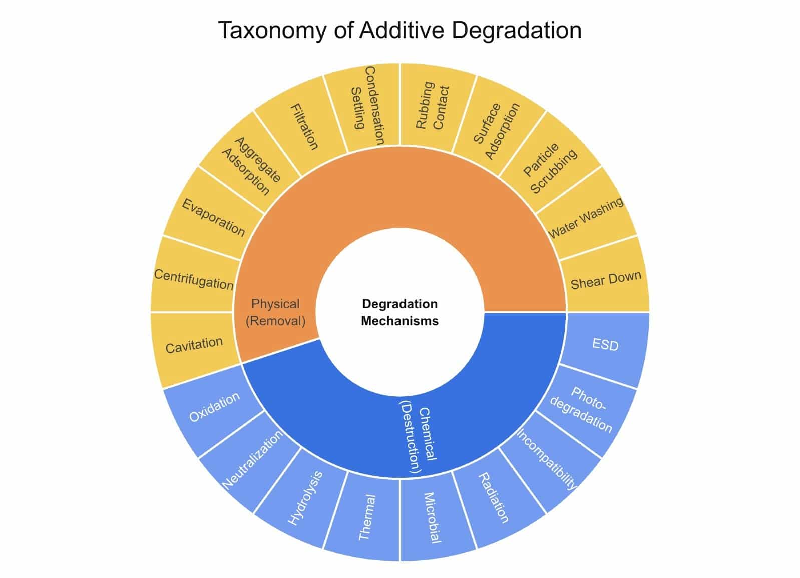
In putting together this article I realised just how many ways an additive can actually fail. I started with some of the requirements of formal lube analysis teaching, but even then realised this was just scratching the surface and in the end I generated a complete taxonomy of lubricant additive degradation mechanisms.
These can be split into two main categories of physical or chemical. Physical meaning the intact additive is removed from the fluid often showing reduced additive detection by ICP for elements like zinc and phosphorus in used oil analysis. In contrast, chemical depletion may or may not show as an element drop as chemical degradation ie neutralisation or hydrolysis (terms I will explain later) mean the elements are still present but not actually functional.
Assessing Risk for Common Additive Depletion Mechanisms
The following mechanisms represent the primary vectors through which additive protection is lost. They are categorized by their fundamental nature: chemical reactions that destroy the additive or physical processes that remove it.
a) Neutralization
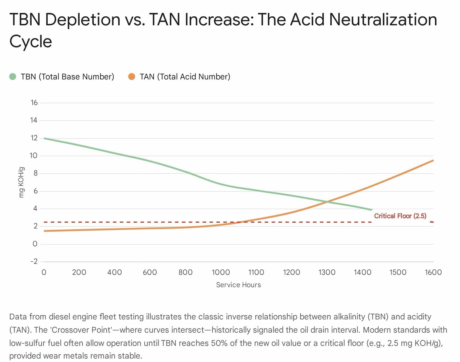
Mechanism: Acid-base neutralization is the primary depletion mechanism for detergents (calcium/magnesium sulfonates, phenates) in internal combustion engines. Combustion produces sulfuric acid (H₂SO₄) from fuel sulfur and nitric acid (HNO₃) from NOₓ. These strong acids react directly with the alkaline carbonate core of the detergent micelle: CaCO₃ + H₂SO₄ → CaSO₄ + H₂O + CO₂.
Risk Assessment: The rate of neutralization is driven by fuel sulfur content and blow-by rates. In modern Ultra-Low Sulfur Diesel (ULSD) applications, the risk has shifted from strong acid neutralization to weak organic acid handling.
- Monitoring: Track the Total Base Number (TBN). A drop to 50% of the new oil value is a common warning limit. The “Crossover Point” where falling TBN meets rising TAN (Total Acid Number) indicates the alkaline reserve is exhausted and corrosion is imminent.
b) Shear Down / Polymer Shear
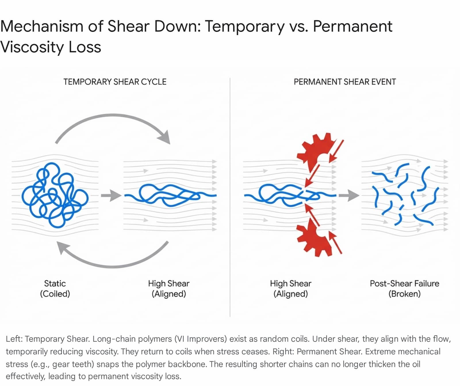
Mechanism: Polymer additives, specifically Viscosity Index Improvers (VIIs), are long-chain molecules that coil and uncoil to manage viscosity. Under high mechanical stress (e.g., gears, hydraulic pumps), these polymer chains can be physically torn apart (scission). This permanent breakage reduces the oil’s viscosity, potentially dropping it out of grade.
Risk Assessment: High-shear applications like engines, gearboxes and high-pressure hydraulic systems are most at risk.
- Permanent vs. Temporary: Distinguish between temporary shear (alignment of molecules, reversible) and permanent shear (breaking of molecules, irreversible).
- Monitoring: Track Kinematic Viscosity at 40 or 100°C. A decrease of >10% often signals shear degradation if no evidence of external contaminants like fuel.
So what is a temporary shear? Temporary shearing occurs when the polymers deform but don’t actually break, lining up with the flow of the fluid to give less resistance to flow. This can be beneficial in certain areas of the system as it helps reduce drag and friction in particularly high speed areas and is not permanent and returns to an increased resistance to flow state when needed. So it is in my opinion not a “true” shear in the terminology and is more a temporary polymer alignment and deformation than a shear which suggests breakage. The original terminology comes as the effect observed looks identical to a shearing additive when in these conditions, but switching to different conditions the viscosity improvement returned – hence the temporary shear. Permanent shear is where the actual mechanical forces truly do cut the polymers into smaller ones.
c) Hydrolysis
Mechanism: Hydrolysis is the chemical breakdown of additives in the presence of water and heat. ZDDP (anti-wear) and Ester base oils are particularly vulnerable. Water attacks the molecule, cleaving bonds to form acidic by-products (sulfuric acid, carboxylic acid) and precipitates (zinc sediments) or reversing the esterification reaction to the original acid and alcohol. As can be seen the acid number increase can be exponentially higher with additives and/or base oils that hydrolyse.
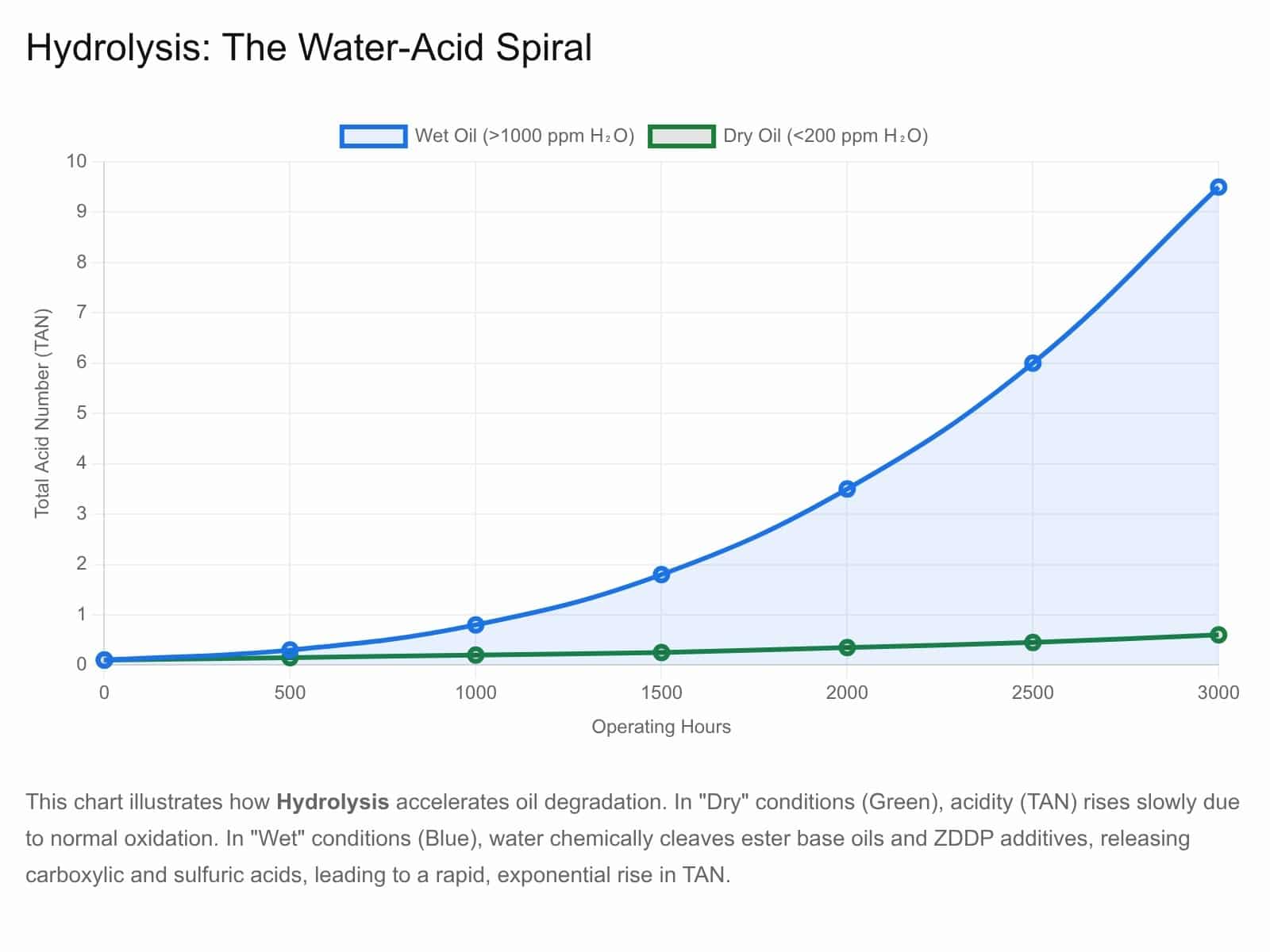
This chart demonstrates the Hydrolysis mechanism, specifically for ester-based fluids or ZDDP additives. In “Wet” conditions (high water content), the water chemically cleaves the additive molecules. This destroys the additive’s function and releases acidic by-products, causing the Total Acid Number (TAN) to spike much faster than in dry conditions.
Risk Assessment: Systems with high humidity or water ingress (steam turbines, paper mills) are at high risk, or simply operate outdoors such as construction and mining equipment.
- Impact: Hydrolysis of ZDDP destroys its anti-wear capability and increases the oil’s acidity (TAN), leading to a “double penalty” of wear and corrosion.
- Monitoring: Routine water content analysis (Karl Fischer), crackle and Acid Number (AN) trending.
d) Oxidation
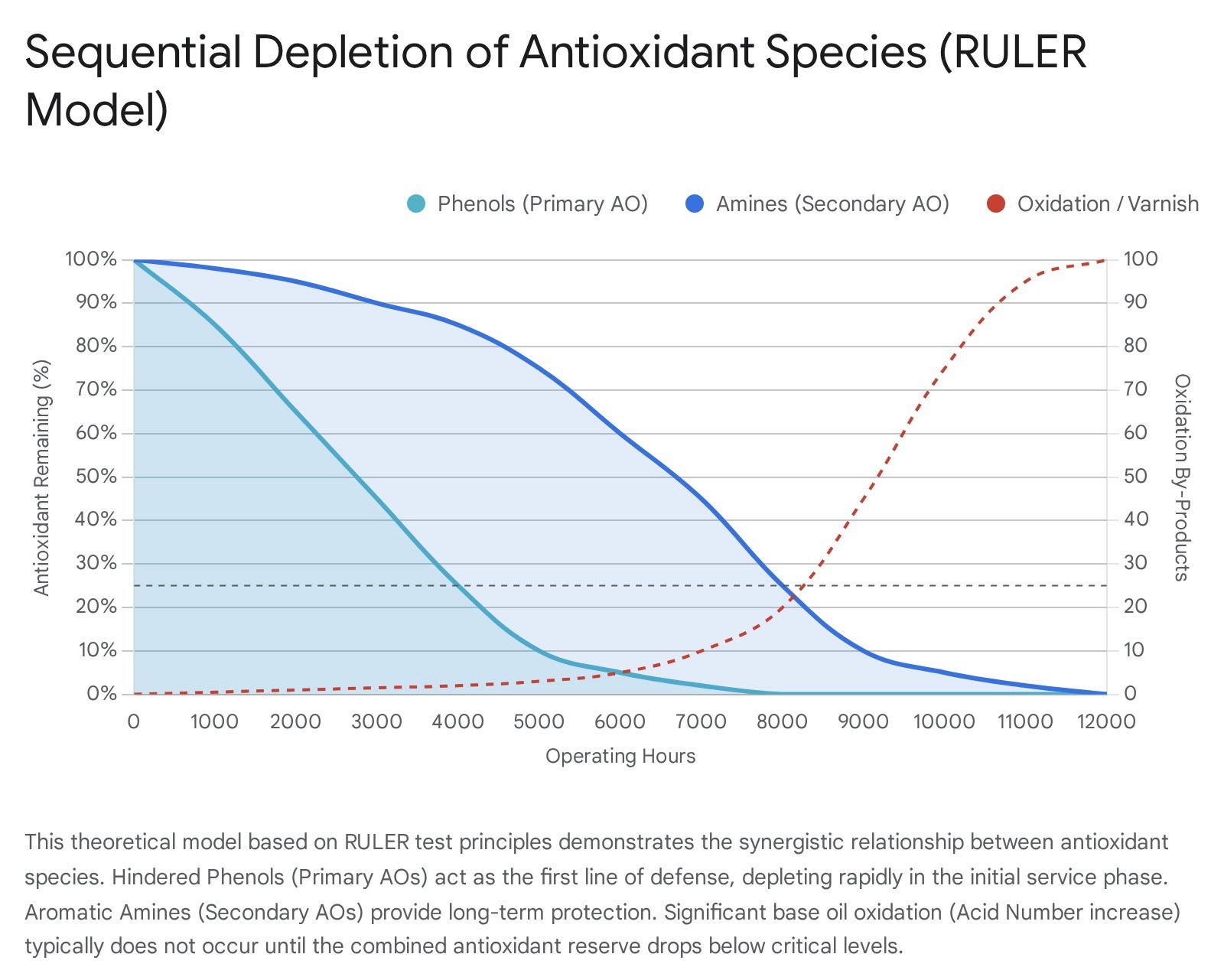
Mechanism: Oxidation is a free-radical chain reaction where oxygen attacks the hydrocarbon molecules. Antioxidants (AOs)—typically phenols and amines—sacrifice themselves to stop this chain reaction. Phenols act as primary radical scavengers (depleting early), while amines act as persistent radical traps (depleting later).
Risk Assessment: High temperature is the primary catalyst; oxidation rates double for every 10°C above normal operating temperatures (especially above 60°C) – the Arrhenius rule – see how the remaining life of the oil additives decreases rapidly with increasing temperature .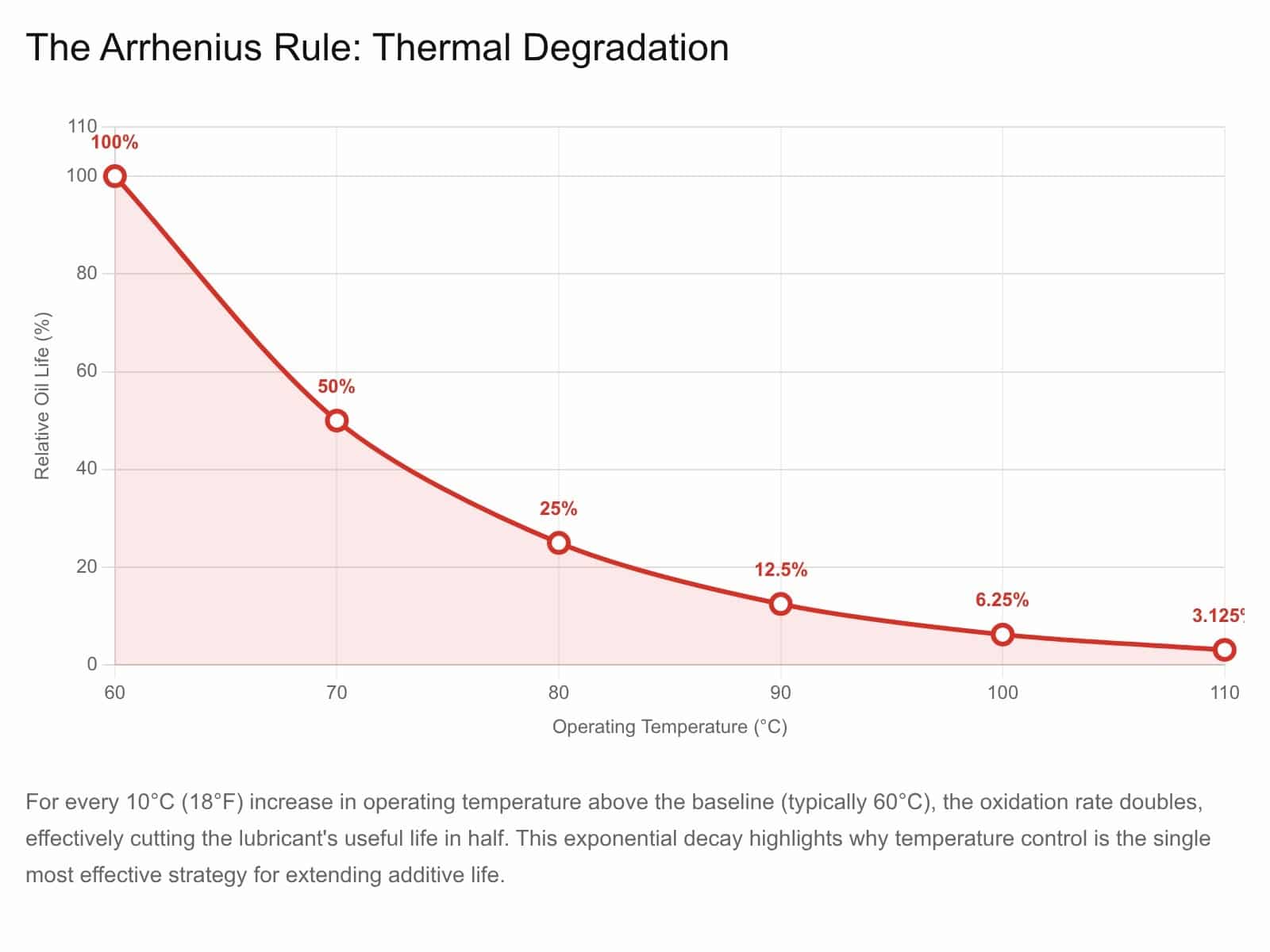
- Monitoring: RULER (Linear Sweep Voltammetry LSV) is a popular test that measures remaining antioxidant concentration directly. RPVOT measures bulk oxidative stability and measures a combination of base oil and additive stability rather than specific additives. In the graph below these show depletion earlier than the traditional tests. However LSV is exceptionally batch to batch specific as the same product name from 3 years ago may have a different additive package now to what it used to and equally mixing different products can make measurements confusing. Hence this is often complimented well by RPVOT oxidation stability as it is not product specific.
- Traditional tests such as acid number, varnish potential and oxidation by FTIR all measure the degradation of the lubricant from the lack of antioxidant additives remaining.
e) Thermal Degradation
Although not directly thermal degradation it’s worth highlighting how oxidisation degradation products deposit which is very temperature dependent.
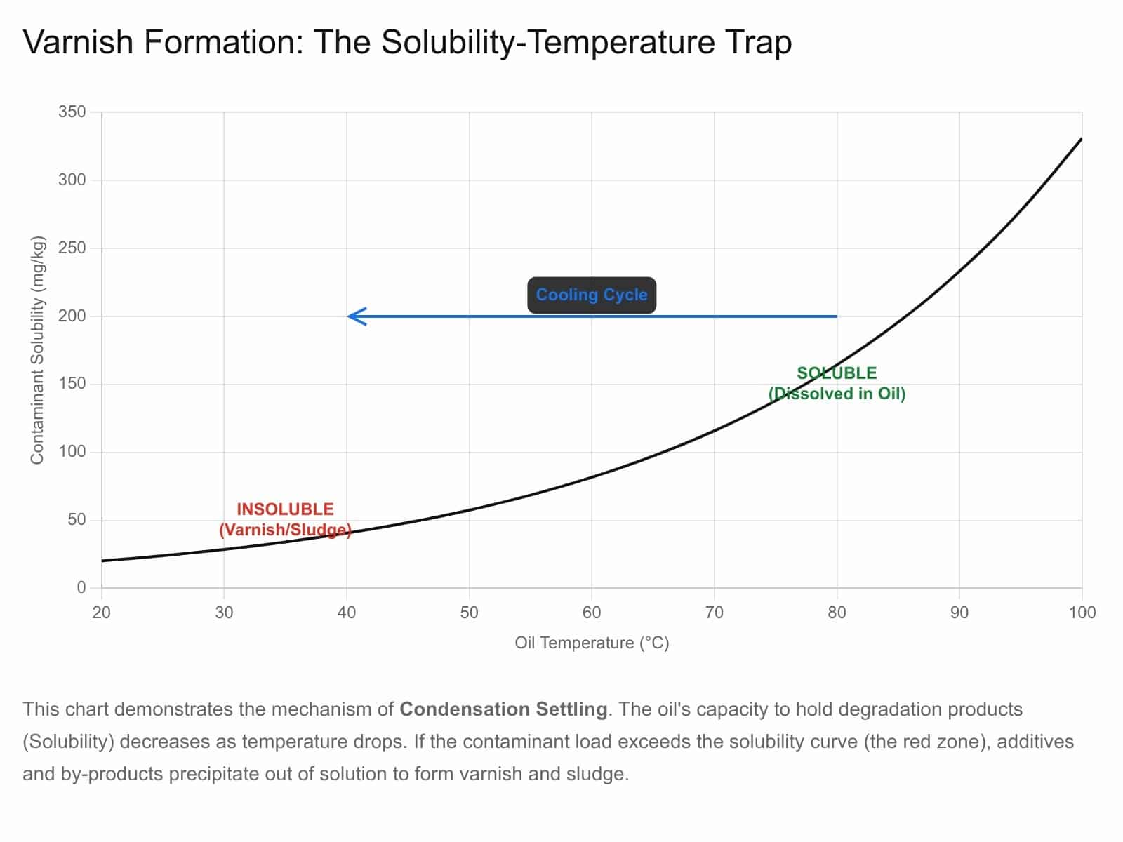
As can be seen the temperature as go from hot to cold can lead to sudden deposition of varnish such as seen in cooling systems leading to insulation and rapid increase in heat build up in the system.
Now returning to thermal degradation.
Mechanism: Unlike oxidation, thermal degradation (pyrolysis) occurs in the absence of oxygen when temperatures exceed the molecule’s thermal stability threshold (often >200°C). This causes molecules to crack (break into smaller parts) or polymerize (link into sludge).
Risk Assessment: Common in systems with “hot spots” like microdieseling (air bubble implosion), heater elements, or high-friction zones. ZDDP begins to thermally decompose at temperatures as low as 150-170°C, forming phosphates that are precursors to tribofilms but depleting the bulk reserve.
f) Water Washing
Mechanism: Polar additives (detergents, rust inhibitors, dispersants) have a natural affinity for water. If water enters the system and forms an emulsion, these additives can partition into the water phase. When the water is removed (by gravity settling or coalescers), the additives are stripped out with it.
Risk Assessment: Critical in turbines and circulating systems with water separators. Aggressive water removal can inadvertently strip the additive package.
- Demulsibility Failure: As polar additives wash out or degrade, they often stabilize emulsions, making it impossible to separate water from the oil. This is normally detected with a ASTM D1401 or IP19 water separability test.
The density and polarity of different additives can be seen further in section n) centrifugation.
g) Particle Scrubbing
Mechanism: Contaminant particles (especially soot in diesel engines) attract polar additives, but also applies to dirt and wear metals or anything that is suspended. Dispersants and to a lesser extent ZDDP adsorb onto the surface of soot particles to prevent them from agglomerating. This effectively removes the additive from the solution; it is “scrubbed” out of the active oil film. These particles are often taken out with filtration which also removes the additives adhered to them. This is important as soot being held in suspension helps reduce resistance to flow, but when the particles agglomerate there can be a viscosity rise up to a point the oil can form temporary or permanent gels – something that is an emergency in diesel engines and something we as a lab screen for on each sample with a high temperature gelling test. Normally the additives can handle 5 or 6% soot, but when scrubbed out the ability to handle can soot can be severely depleted.
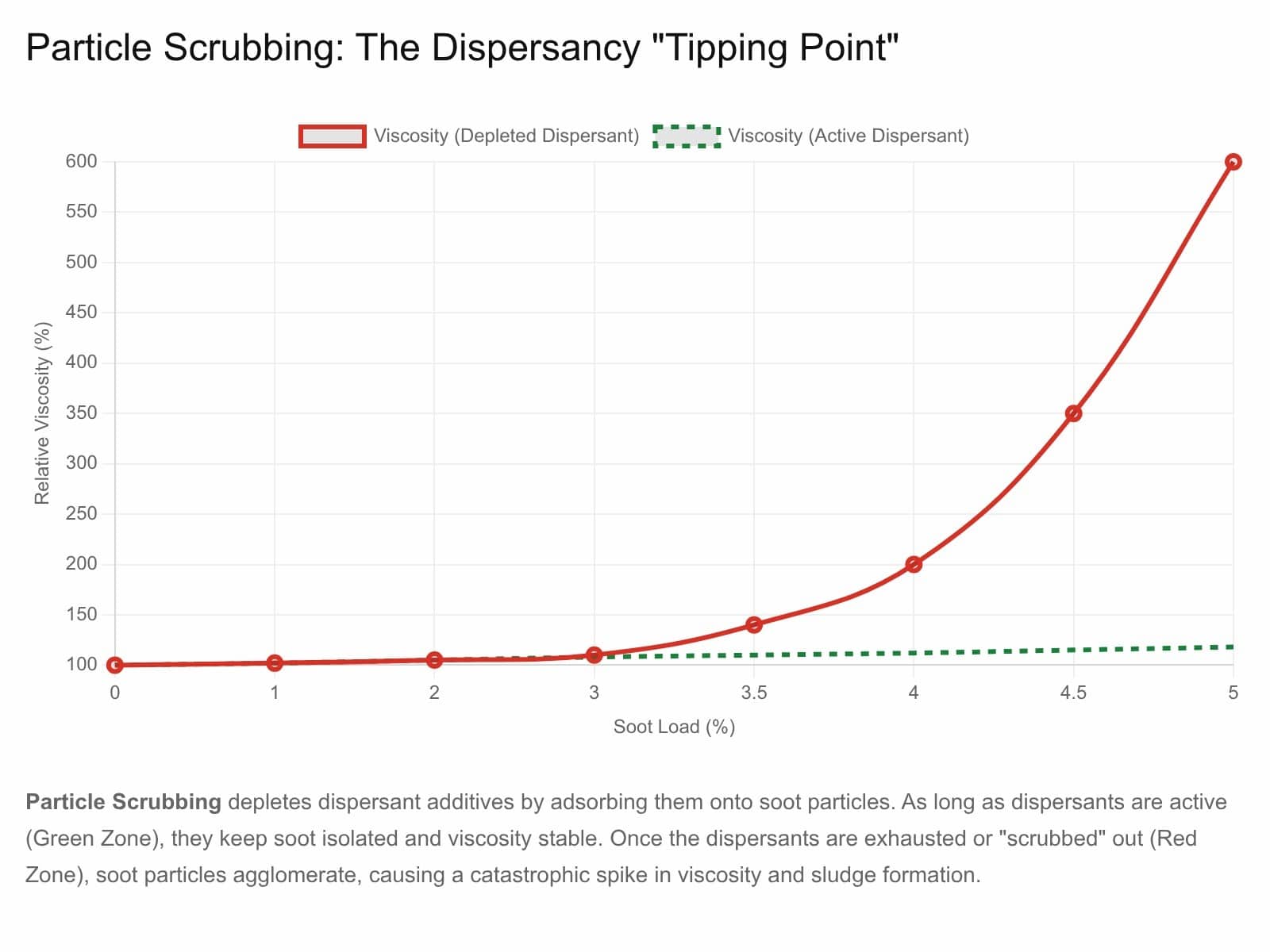
This graph illustrates Particle Scrubbing and Dispersant Depletion. • Green Line (Active Dispersants): The additives envelop soot particles, preventing them from sticking together. Viscosity remains stable even as soot load increases. • Red Line (Depleted Dispersants): Once the dispersants are “scrubbed” or consumed by the particle load, they can no longer isolate the soot. The soot particles agglomerate (stick together), causing a rapid, catastrophic spike in viscosity.
Risk Assessment: High-soot environments (EGR engines) see rapid depletion of dispersancy. Once the dispersant capacity is overwhelmed, soot agglomerates to form abrasive sludge.
- Monitoring: Blotter Spot Test for dispersant and FTIR for soot loading, pentane insolubles and soot by Thermogravimetric analysis all monitor the same thing.
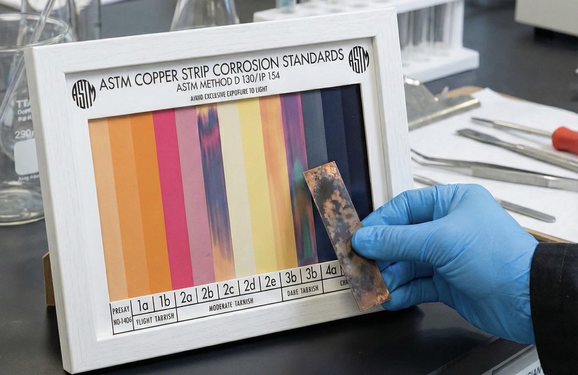
It’s worth noting that very high corrosion or buildup of wear particles can deplete anti-wear additives in a similar manner. This is very common in loaded gears such as differentials and final drives and one of the common mechanisms observed is an almost sooted appearance to the sample. This is a colloidal material but instead of being soot it is metal sulphides which are dark black coloured. This is a classic sign of “old wear” as opposed to fresh wear which will be nice and shiny metal pieces. Sometimes these effects can be self propagating such as copper which is dispensable in oil and in engines you often have leaching effects. This leaching not only removes copper into the oil but also depletes additives. An extreme source of this would be extreme pressure additive dissolving the copper. Hence additional tests of copper corrosion are often useful measures for lubricant propensity to cause corrosion.
h) Surface Adsorption
Mechanism: Anti-wear (AW) and Extreme Pressure (EP) additives function by adsorbing onto metal surfaces to form protective films. However, this is a competitive process. Polar contaminants or degradation products can “out-compete” the additives for surface space, blocking them from protecting the machine.
Risk Assessment: In systems with high varnish or sludge potential, the polar varnish precursors coat metal surfaces, rendering the AW/EP additives ineffective even if they are present in the bulk oil.
i) Rubbing Contact
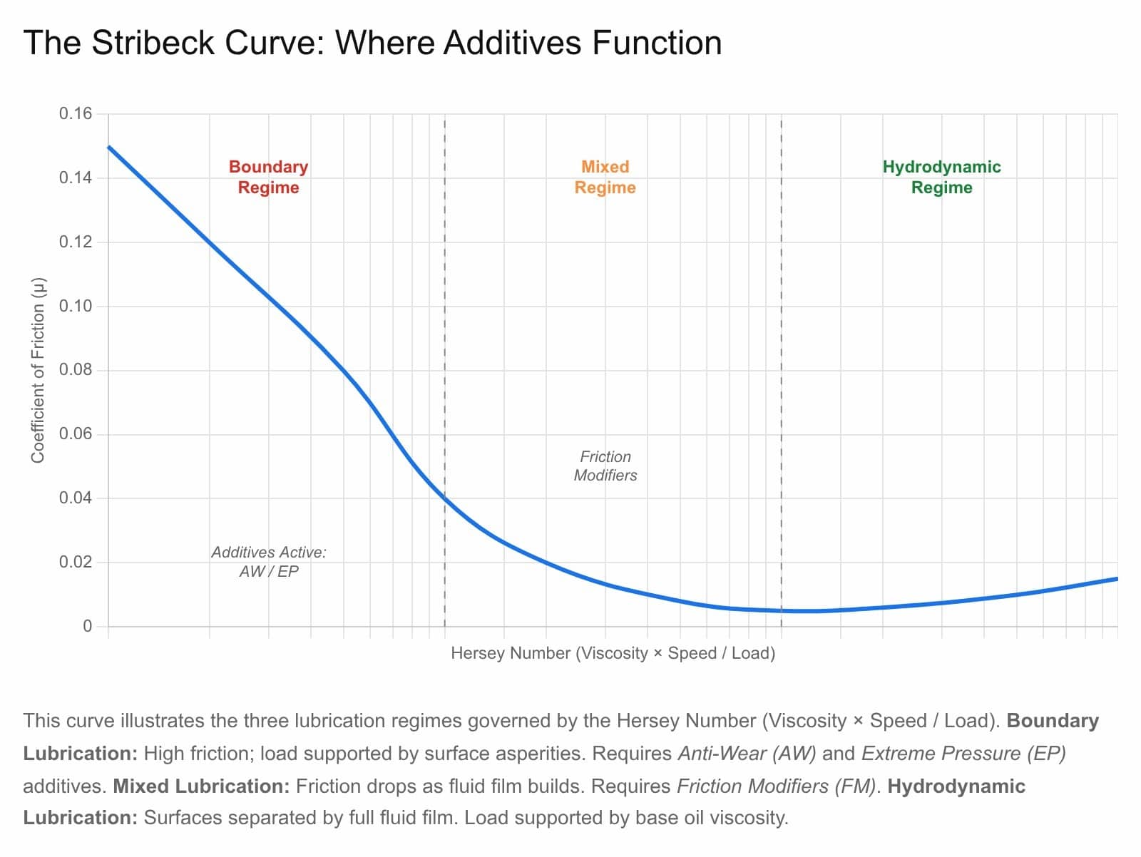
Mechanism: This is the intended “sacrificial” mode of AW/EP additives. Under boundary lubrication conditions (metal-to-metal contact), frictional heat drives a reaction between the additive (e.g., ZDDP) and the metal surface to form a sacrificial Tribofilm (e.g., polyphosphate glass).
Risk Assessment: Heavy loads, stop-start cycles, and slow speeds increase boundary contact, accelerating the consumption of these additives.
- Tribochemical Wear: As the tribofilm is worn away, it must be continuously replenished from the bulk oil reserve.
The point at which additives are used and hence depleted most is highlighted in the stribeck curve, for instance boundary lubrication uses up ZDDP antiwear additive faster than full hydrodynamic lubrication.
j) Condensation / Wax Settling
Mechanism: Additive solubility is temperature-dependent. During storage or downtime, if temperatures drop, certain additives (like some specific EP chemistries or high-MW polymers) may become insoluble and precipitate out of the solution to the bottom of the container. This is often termed “additive dropout”. This is extremely common with cold spells for pour point depressants that can be overwhelmed and then stay in the wax phase, but the top non waxed fluid remains vulnerable.
Risk Assessment: Bulk storage in cold climates is a major risk factor. Using the “bottom” of a tote or drum that has suffered dropout can introduce a super-concentrated sludge that clogs filters, while the top layer is additive-deficient.
k) Filtration
This is often surprising to most as cleaner oil just sounds better the cleaner you go, but with finer filtration often comes the challenge of removal of additives which need replacing for best lubricant function. The graph below represents a reasonably well dissolved additive like ZDDP, but additives such as silicone antifoam can be stripped at even larger sizes owing to their poor solubility in the lubricant.
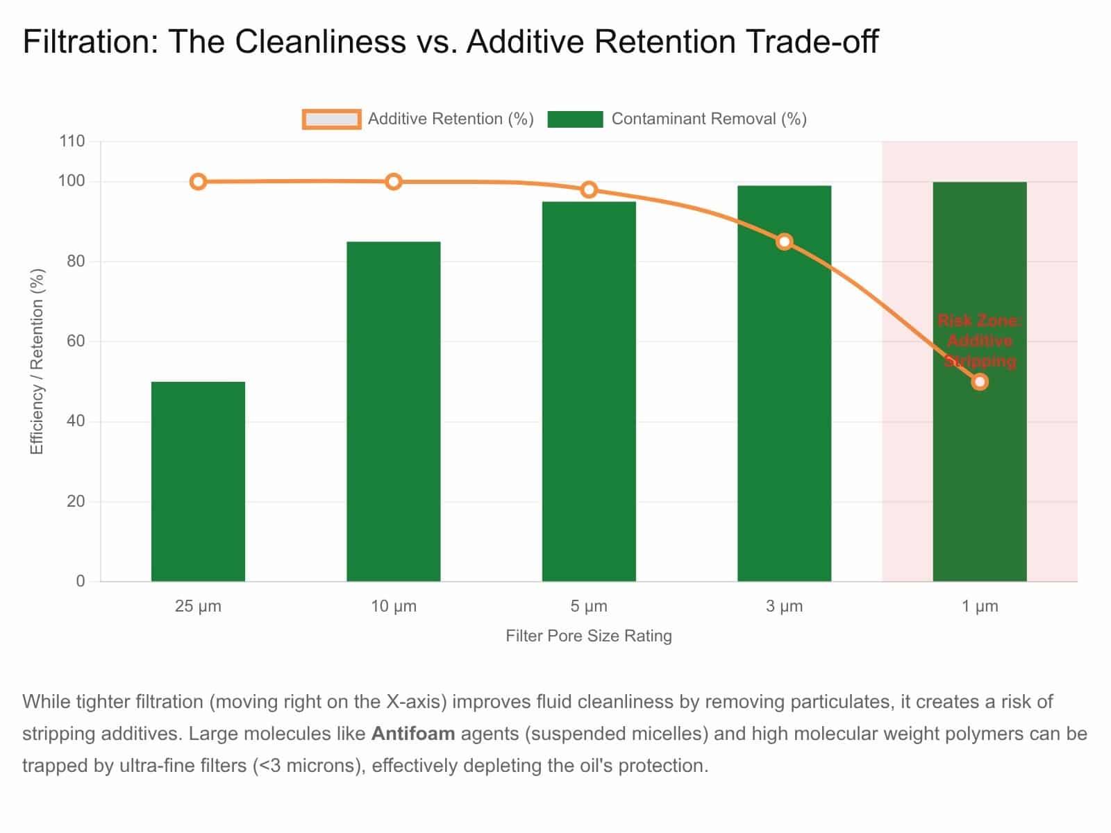
Mechanism: While essential for cleanliness, fine filtration can strip specific additives.
- Solid Additives: MoS₂ (Molybdenum Disulfide), Graphite, or PTFE particles are solids and will be trapped by fine filters (<5 microns).
- Antifoam Agents: Silicone antifoams exist as microscopic suspended droplets (micelles). Aggressive filtration can strip these droplets, leading to foaming issues.
- Adsorption: Cellulose or active media (like Fuller’s Earth) can chemically adsorb polar additives like rust inhibitors.
l) Aggregate Adsorption
Mechanism: This specifically relates to Dispersants. Dispersants form micelles around contaminants to keep them suspended. When the contaminant load (soot, sludge) is high, the dispersants form aggregates around these particles. These large aggregates can then be removed by filtration or settling, taking the dispersant additives with them.
Risk Assessment: This creates a “tipping point” where dispersancy suddenly fails, leading to rapid sludge precipitation.
m) Evaporation
Mechanism: In high-temperature zones (pistons, turbo bearings), volatile “light ends” of the base oil and specific additives can vaporise. Phosphorus (from ZDDP) and certain antioxidants are prone to volatility.
Risk Assessment: High volatility leads to oil thickening (viscosity increase) and alters the chemical balance of the remaining fluid. In engines, volatilised phosphorus can poison catalytic converters.
- Monitoring: Noack Volatility Test (ASTM D5800).
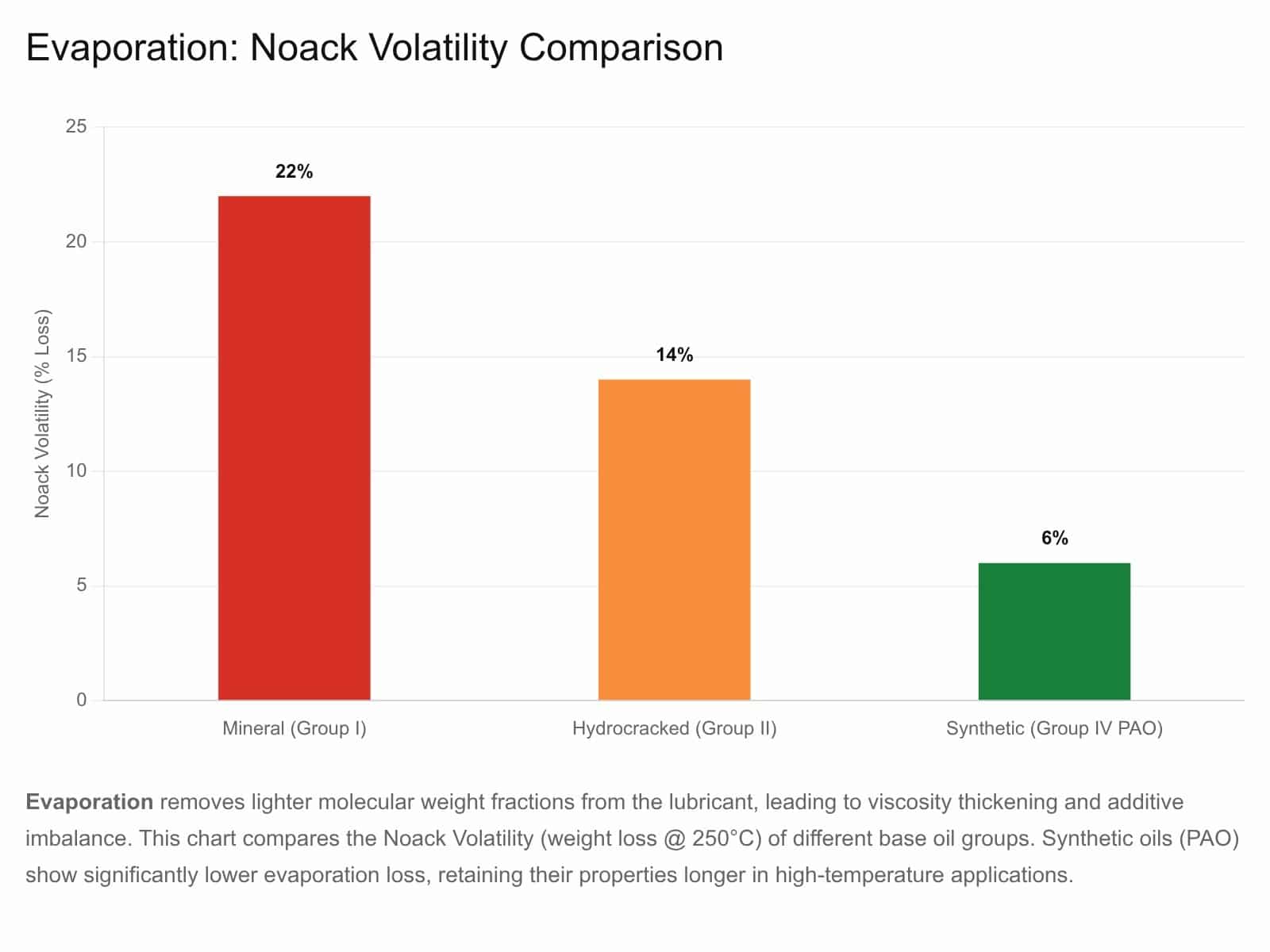
The above chart visualizes Evaporation and Volatility. Lighter fractions of the base oil and specific volatile additives (like phosphorus species) vaporise at high temperatures. High volatility leads to oil thickening (viscosity increase) and additive imbalance, as well as downstream catalyst poisoning in engines.
n) Centrifugation
Mechanism: Centrifugal separators generate thousands of Gs of force. While effective for removing water/dirt, they can separate additives based on density. High-density additives (like calcium sulfonates or solid lubricants) can be forced out of solution if the centrifuge is operated aggressively or if the additive solubility is marginal.
Risk Assessment: Common in marine applications. “Over-purification” can strip the TBN reserve from the oil.
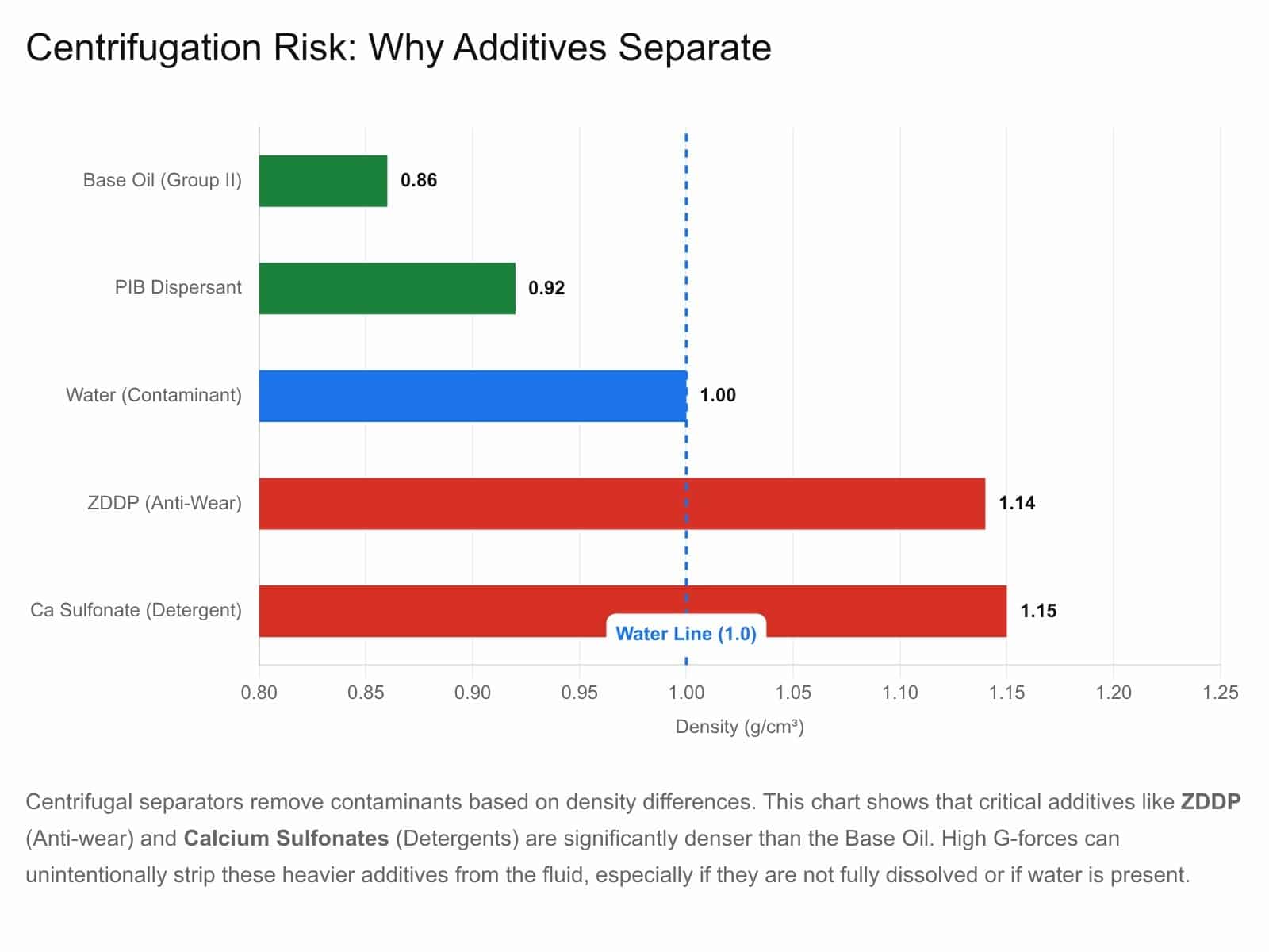
Centrifuges separate contaminants based on density. However, many critical additives (like ZDDP and Detergents) are significantly denser than the base oil. If the centrifuge is operated at too high a G-force or if the additives are not fully soluble, they can be “purified” out of the oil along with the water and dirt.
o) Microbial Degradation
Mechanism: Bacteria and fungi can thrive in oil systems contaminated with water. These microbes feed on the carbon in the base oil and the phosphorus/nitrogen in the additives as nutrients.
- Consequence: They chemically degrade the additives and produce acidic by-products and biomass (slime) that clogs filters and corrodes metal.
p) Radiation Degradation
Mechanism: In nuclear power applications, ionizing radiation (gamma rays, neutrons) attacks the molecular bonds of both base oil and additives.
- Consequence: This causes cross-linking (polymerization) or chain scission, often rendering standard antioxidants ineffective. Phosphate esters and fluorinated oils are monitored for rapid acid increase under radiation.
q) Electrostatic Discharge (ESD)
Mechanism: Modern high-velocity hydraulic systems using non-conductive (Group II/III, IV) oils can generate static electricity as oil passes through filter elements.
- Consequence: When this static discharges (sparks), it creates localized temperatures >10,000°C. This “micro-lightning” cracks additive molecules and generates free radicals, acting as a potent catalyst for varnish formation.
r) Incompatibility (Chemical Reaction)
Mechanism: Mixing incompatible lubricants can cause immediate additive depletion.
- Example: Mixing an acidic rust inhibitor with a basic detergent can cause a neutralization reaction, precipitating both additives out of solution as a salt (soap). This creates a “chemical clot” that blocks flow and removes protection.
s) Cavitation (Microdieseling)
Mechanism: Vapor bubbles form in low-pressure zones and collapse violently in high-pressure zones. The collapse generates adiabatic micro-hotspots (>1,000°C).
- Consequence: This localized heat causes thermal-oxidative degradation of additives surrounding the bubble, leading to soot formation and nitrogen fixation (nitration).
t) Photodegradation (UV)
Mechanism: Ultraviolet radiation can break chemical bonds in mineral oils and specific light-sensitive additives.
- Consequence: Formation of chromophores (color bodies) and free radicals that initiate premature oxidation. This is particularly relevant for lubricants stored in translucent containers outdoors or in specific UV-curing manufacturing environments.
2. Risk Assessment Matrix
The table below summarizes the degradation mechanisms and their primary risk indicators.
| Mechanism | Primary Driver | Target Additives | Risk Indicator / Detection |
|---|---|---|---|
| Neutralization | Acids (H₂SO₄, HNO₃) | Detergents (TBN) | TBN dropping <50%, TBN/TAN Crossover |
| Oxidation | Heat + Oxygen | Antioxidants (Phenols/Amines) | RULER Test (AO depletion), RPVOT drop |
| Shear Down | Mechanical Stress | VI Improvers | Perm. Viscosity Loss (>10% drop @ 100°C) |
| Hydrolysis | Water + Heat | ZDDP, Esters | High Water (Karl Fischer), High Acid (TAN) |
| Thermal | Heat (>200°C) | All Organic Additives | Microdieseling (Soot), FTIR Nitration |
| Water Washing | Water Emulsion | Polar Additives (Rust/Detergent) | Poor Demulsibility, Precipitate in Sump |
| Particle Scrubbing | Soot / Dust | Dispersants, ZDDP | High Soot Load, Blotter Spot Test |
| Filtration | Fine Pore Size | Antifoam, Solid Lubricants | Foaming issues, Low Silicon (Si) count |
| Centrifugation | G-Force | High-Density Additives | TBN drop across separator, sludge analysis |
3. Conclusion
Additive depletion is not a single phenomenon but a complex web of chemical and physical interactions. While some depletion (like Neutralization and Rubbing Contact) is intentional and beneficial, mechanisms like Particle Scrubbing, Hydrolysis, and Filtration represent “wasted” protection—additives removed before they can perform their job.
For the reliability engineer, the goal is not to prevent depletion entirely, but to manage it. By controlling the catalysts—heat, water, and particles—and using advanced molecular lab analysis (like ICP, acid number, base number, RULER and FTIR) you can ensure that your additives sacrifice themselves for the machine, and not through poor lubricant management.